
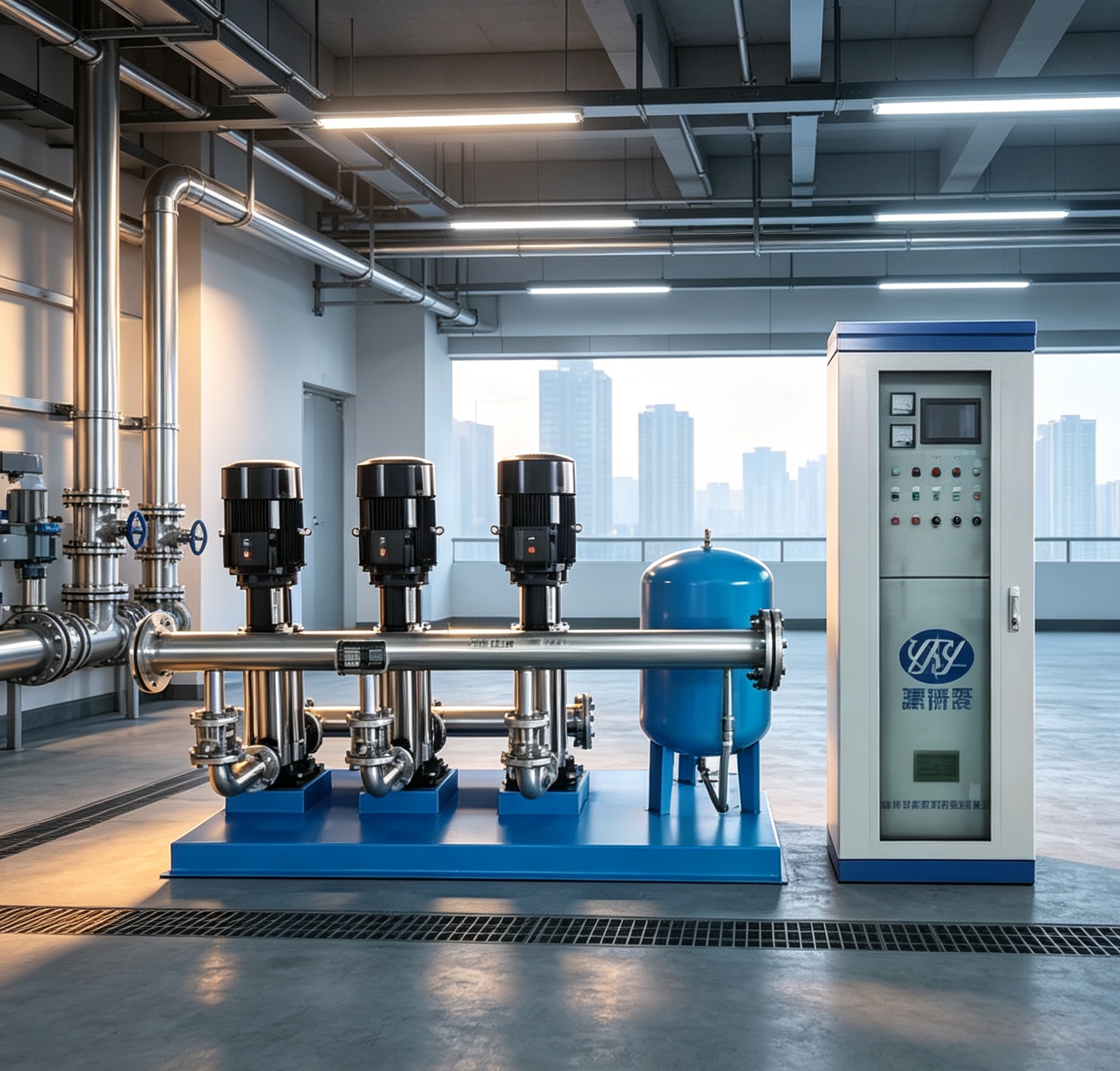
Variable-frequency pump set
Duty/standby arrangement and motor power follow the approved hydraulic schedule.
PROJECT-CONFIGURED BOOSTER SYSTEM
YHB draws from a clean storage tank or inlet main and keeps the outlet setpoint stable as demand changes. Variable-frequency control stages pumps automatically, reducing unnecessary energy use and simplifying the pump room interface.
WORKING PRINCIPLE
The controller reads the outlet pressure continuously and adjusts pump speed and staging to the actual demand.
Water enters from the clean tank or inlet main through the suction manifold.
A pressure transducer sends outlet feedback to the PLC and VFD controller.
Pump speed and duty/standby sequence follow the live demand curve.
The setpoint is maintained at the outlet while alarms and protections remain active.
SELECTION DATA
Share the values you know. Our engineering team can identify the gaps before the final model, pump duty and interface schedule are issued.
SYSTEM COMPONENTS
Duty/standby arrangement and motor power follow the approved hydraulic schedule.
Outlet feedback gives the controller the signal required for constant-pressure operation.
Automatic staging, soft start, fault alarms and manual backup control.
Factory-assembled suction/discharge pipework simplifies the pump room interface.
Overload, short circuit, phase loss, overheat and over/under-voltage protection.
IoT/4G remote status and alarm reporting can be included when required.
TYPICAL APPLICATIONS
For building and site water-supply projects, with the booster arrangement selected around demand, inlet conditions and the required pressure setpoint.
Daily domestic demand
Configured around the required flow, head and pressure setpoint.
Continuous occupancy
Configured around the required flow, head and pressure setpoint.
Variable process demand
Configured around the required flow, head and pressure setpoint.
Remote network pressure
Configured around the required flow, head and pressure setpoint.
Share the hydraulic values you know. Enter “Please advise” where the project still needs engineering review.